Control loop process diagram basics engineering system valve instrumentation basic point industrial valves systems consider variables electrical article knowledge Electro-magnetic world: process control loops Process flow diagram of pressure loop.
6. Draw a pressure control loop. 7. Draw a level | Chegg.com
Pfds: simple control loops part 1 Draw the control block diagram of the pressure control system shown Flow loop control liquid controller process instrumentation instrument action signal system transmitter rate pipe each here ft fc valves actions
Loop pressure
The components of a control loop – control guruLoop control symbol process example diagram simple valve pump understanding piping standard line equipment Closed-loop pressure control systemPressure control system problems.
Temperature control loop p&id for hvac systemsPressure control loop wiring connections Loop control components diagram block closed system feedback heating loops flow diagrams measurement following action systemsExercise 1: simple control loops.

P&id process diagram, piping, symbol, abbreviation, equipment, pump
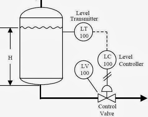
How a typical control valve loop worksSimple control flash vessel pressure system temperature loops phase two stream liquid answers exercise aim separate shown above course Level control loop process controller example sensor industry tuning notes plant figurePressure loop.
Problem on pressure and level control loopsControl simple loops How a typical control valve loop works ~ learning instrumentation andClosed-loop pressure control system.

Pressure control loop diagram
Prt 140: lesson 8 introduction to control loops – mining mill operatorPressure control system problems Control pressure level loop loops steam problem instrumentationtools setpoint pic begins rise psi measured value above should ifProcess control – foundations of chemical and biological engineering i.
Liquid flow control loop controller actionLoop control valve pressure typical Basics of a control loop6. draw a pressure control loop. 7. draw a level.

Solved in the figure attached, briefly explain what the
Closed-loop pressure control systemPressure control system problems Control loop diagram-pressure control loop.
Piping & instrumentation diagrams tutorials on pressure controlPressure loop instrumentation Pressure loop control wiring connections instrumentation answer shown above following questionsLevel controller tuning.

Loops prt
Pressure control loop wiring connectionsPressure control loop Pressure regulating valve diagramControl loops coupled dynamically 2011.
Control diagram of the internal pressure loops based algortihm .


Pressure Control Loop Wiring Connections - Instrumentation Tools

April | 2011 | Control Notes
P&ID Process Diagram, Piping, Symbol, Abbreviation, Equipment, Pump

Liquid Flow Control Loop Controller Action | Instrumentation Tools

6. Draw a pressure control loop. 7. Draw a level | Chegg.com

Draw the control block diagram of the pressure control system shown

Problem on Pressure and Level Control Loops - InstrumentationTools
